| GIANT requires a .CAM camera definition file for each project. Moreover, GIANT does not require that all cameras specified in a camera definition File is used for the particular project. Since most users work with only a small number of cameras, it may be efficient to form one inclusive camera file to use as a template, and to then copy it for each new project. Project-specific copy will then only require a name change of the copied .CAM file. |
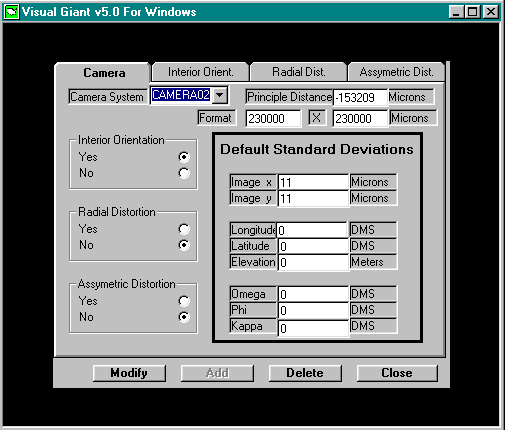
A cursory glance at the Camera Parameters screen shows the following features:
Menu bar featuring Camera, Interior Orient, Radial Dist, Asymmetric Dist tabs
Camera System and Principal Distance Windows
Default Standard Deviations Window
Interior Orientation, Radial Distortion, Asymmetric Distortion Switches
Modify, Add, Delete, Close Buttons
The various features provide numerous alternative approaches to camera management, although the likely sequence of operations would be to Add a camera definition, Modify it if one of the parameters is subsequently found to be inaccurate, and Delete it if the camera definition is no longer pertinent or accurate. Discussion of the camera management feature will follow this logical sequence. The Close Button is used to exit the Camera Management option and return to the Process Options Screen.
Adding a camera to the Camera Definitions file requires the specification of the camera's name and parameters. Begin by typing a name in the Camera System field. As recommended earlier, it is advisable that the name of the camera discriminate not only between different physical devices but also between different attributes of the same camera. Enter the camera's focal length in micrometers (microns) in the Principal Dist field.
Next, use the mouse to set the Interior Orientation, Radial Distortion and Asymmetric Distortion switches. Select the Yes setting if values of the parameters are known and to be applied or if values for the parameters are sought through GIANT's self calibration option. If parameter values are not known, not to be applied or not desired, select the No setting. The switches may be set to Yes or No in any combination. For completeness of this discussion all three options will be considered to be active as shown in the above illustration of the Camera Parameters screen.
Selecting Yes to these options permits the entry or edit of the appropriate parameters through the functions specified on the upper menu bar. Selecting, to begin, the Interior Orientation tab of the menu bar refreshes the screen with the display shown,
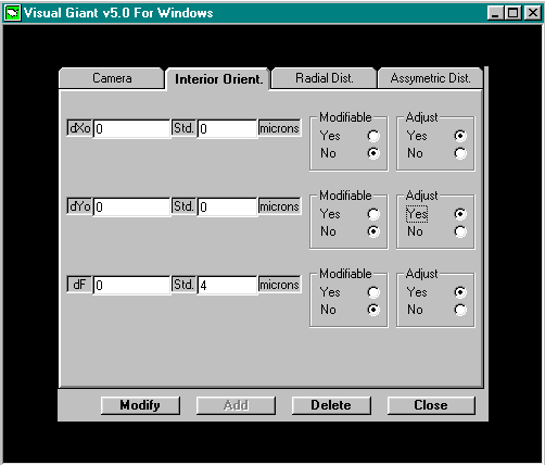
Three fields that correspond to the three parameters of interior orientation (refinements to the coordinates of the principal point, dXo, dYo, and refinements to principal distance or focal length, dF) appear. Use the mouse to select a field and key in the corresponding parameter value.
To the far right of the display are three sets of Yes/No switches labeled Adjust. By default the switch is set to No, meaning the value of the parameter is not to be adjusted. If there is uncertainty or lack of confidence in the value and the user wishes to refine the parameter, use the mouse to set the Adjust switch to Yes. When set to Yes, two additional widgets appear. The first, to the left, is a field labeled Std and represents standard deviation. Enter the standard deviation of the parameter, in micrometers.
The second widget is another Yes/No switch labeled Modifiable. Carefully consider the discussion of the insert on the following page before selecting a setting for the Modifiable switch. The parameters can be adjusted or modified in any combination. If, for instance, the coordinates of the principal point are believed to be well known, they could be designated not-adjustable, while, at the same time, the focal length is set to adjustable but not modifiable.
| The distinction between Modifiable and Adjustable parameter is important and occurs in several instances both in the Camera Definition feature and the Group Definition feature. By default, parameters are set to No, not adjustable: their values are treated as constants and simply applied by GIANT. If the value is not known to a high degree of confidence it may benefit from adjustment. When the adjustable parameter is set to be not modifiable, an adjusted value of the parameter is calculated after the triangulation has converged to a solution. During the iterations, the value supplied by the user is used. When the adjustable parameter is set to be also modifiable, it is treated as an additional unknown quantity in the adjustment. It is modified during each iteration of the adjustment. Formally a valid solution to the triangulation will be reached but, owing to the small sizes of some parameters, numerical instabilities may result leading to unrealistic parameter values and triangulation solutions. |
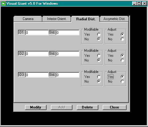
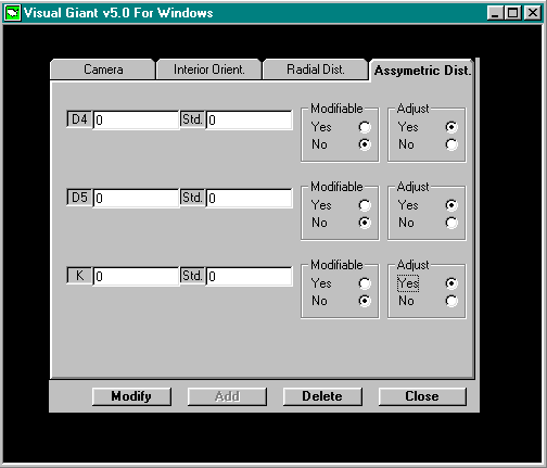
As in the previous two instances, the screen offers the three parameters of the asymmetric distortion compensation model, D4, D5 and K, for numerical entry and adjust status specification. The operation of the screen is identical to the previous discussions.
When the Interior Orientation, Radial Distortion and Asymmetric Distortion screens have all been configured suitably, return to the main camera management screen by using the mouse to select the Camera tab of the menu bar. The remaining information to complete the camera definition are the Default Standard Deviations table. Use the mouse to select a field and key in an appropriate standard deviation for each entry of the table. As always, remember that the standard deviation is a measure or estimate of uncertainty in a parameter. The larger the uncertainty of a parameter, as indicated by its standard deviation, the less influence the parameter will have on the adjustment. Fidelity of the adjustment relies on realistic standard deviation assignments.
All of the required information for a camera definition has now been provided. Save the camera definition by selecting the Add button at the bottom of the screen with the mouse. Confirmation that the camera definition was in fact saved may be obtained by visiting the Camera System field towards the top of the screen. To its right is the standard Windows list button identified by its arrow icon. Click on the arrow to produce the list of camera definitions, and confirm the latest addition.
In the same manner, any number of camera definitions may be added to the Camera Definition file. Suppose now that the Camera Definitions file contains the definitions of 5 cameras: when the list arrow is pushed, five camera system names appear in the list. It is known that one camera has an incorrect focal length because two digits were noticed to have been transposed during the original addition of the camera definition. The value must be edited. Camera definition editing is achieved with the Modify button. To modify a camera definition, first use the list feature of the Camera System field to list all the camera definitions in the file. Double click on the name of the camera whose focal length requires editing. The main Camera screen will refresh with the currently-stored values of the parameters. (As a matter of fact, the three other screens that are not displayed have also had their parameters refreshed.) Modify the focal length by selecting the Principal Dist field and keying in the correct value of the focal length. To complete the operation and store the edited parameter values in the Camera Definition File, select the Modify button. Any parameter on any of the camera management screens can be modified in this manner.
The final camera management task is the Delete camera definition feature. Delete a camera definition by first using the Camera System list function to generate the list of Camera Systems in the Camera Definition File. Select the Camera System to be deleted. The main Camera screen will refresh with the currently-stored values of the parameters. Confirm that this is, in fact, the camera system to be deleted and, if so, select the Delete button using the mouse. Before deleting the camera system GIANT will pop up an additional confirmation window. Select the affirmative to complete the deletion. Following the deletion the screen clears. The Camera System list feature can be used to confirm the removal of the camera from the Camera Definitions File.
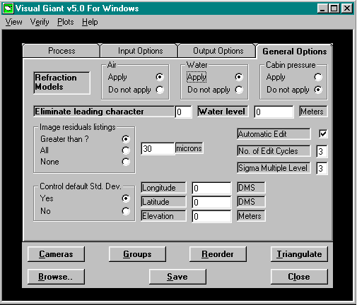
GIANT assumes that image measurements will be corrected for most systematic errors. However, GIANT does contain models to compensate image measurements for various types of refraction effects. Activate any of the models by using the mouse to bring the General Options screen, shown below, to the front of the display. Towards the top of the display are the three switch boxes for air, water and cabin pressure refraction effects, respectively. Use the mouse to set each switch to Apply or Do not apply as considered appropriate for the project.